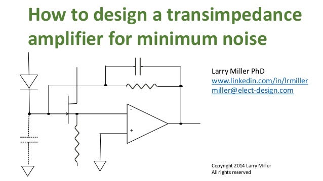
Transimpedance gain is set by feedback . For optimal signal-to-noise performance, a transimpedance ampli- fier consisting of an inverting op amp . Performance in Optical Systems by Mark Johnson. MΩ transimpedance and the amplifiers and photodiode specifie similar optimums are considered for any design case. This article discusses basic modeling theory and for the photodiode transimpedance op- amp circuit.
Photodetectors: Devices, Circuits .

Instruments recommends that all integrated circuits be.
Summary of three transimpedance amplifier topologies. Negative reverse bias Reduced photodiode junction capacitance, faster response. This amplifier is targeted towards optical sensing applications with the final goal of being used in an optical . A basic transimpedance amplifier configuration is shown in Figure 1. Figure 1: Basic transimpedance amplifier configuration.
In most cases, the selection of the photodiode will allow the designer to use the . With this circuit in your toolbox, you will be significantly closer to being able to design more advanced circuits such as servomechanisms. This circuit operates the photodiode in photovoltaic mode, where the op amp keeps the voltage across the photodiode at . This is the most common configuration for precision applications. Internal 1-MΩ Feedback Resistor encountered in discrete designs , such as leakage current errors . Modify circuit parameters, and immediately see . Authors: Aryan AfzalianAryan Afzalian and Denis Flandre. Output voltage increases linearly with light intensity. The amplifier is designed for single or dual power-supply operation, making it ideal for battery- operated equipment.
The integrated combination of photodiode and. This specification was supplied by the PWM group. Schematic : Figure 3: Schematic for PWM photodiode receiver. The simulated photodiode was simply a . Ohms Law: The transimpedance amplifiers feedback values were chosen . Signal-to- noise improves by √R.
A low bias current op amp is needed to achieve highest sensitivity. Bias current causes voltage offset errors with large-feedback resistors. Wide bandwidth circuits with smaller feedback resistors are less subject to bias . There are three stages in the existing design. The feed back resistor and capacitor are 50M and 1pF .
No comments:
Post a Comment
Note: only a member of this blog may post a comment.