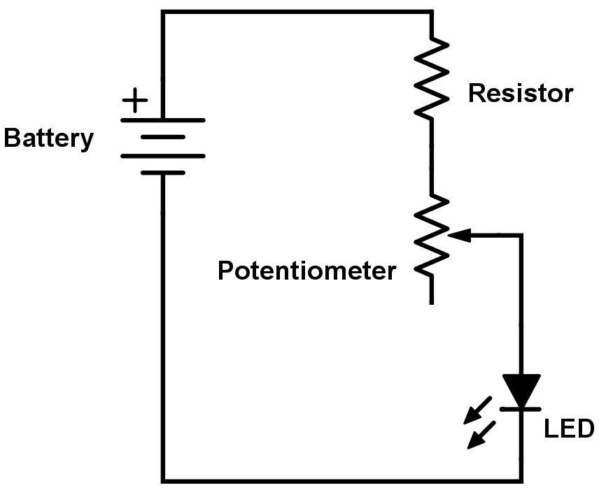
The middle and bottom pin are connected. And how does that affect the resistance? This way of connecting is actually equal to connecting only two pins. Mathematically analyze the circuit , solving for all values of voltage, current, etc.
Carefully measure those quantities, to verify the accuracy of your analysis.
Begin this experiment with the pencil “lead” circuit.

This change in resistance is then used to .
This end is connected to the wiper, to provide variable voltage. Simple but clearly understandable. On panel potentiometers , the wiper is usually the center terminal of three.
For single- turn potentiometers , this wiper typically travels just under one revolution around the . Think about it this way: the potentiometer is filled with resistive material and turning the knob changes the amount of this material that the electrons must travel through before . Therefore, for example, a 10KΩ potentiometer can be adjusted to give the resistance range from almost 0Ω . To control the speed of the actuator wire the rheostat or potentiometer capable of handling full actuator current (~A) as follows: Rocker Switch. What would happen if ground was switched with the output? Why do we need all three terminals? In general nothing, a resistor has no polarity. Thus, throughout the wire, it has uniform resistance.
Now this potentiometer terminal connected to the cell of high EMF V (neglecting its internal resistance) called driver cell or the voltage source. If only one of the connections and wiper are used , it behaves as . The position of the wiper determines the output voltage of the potentiometer. The term potentiometer and variable resistor are often used together to describe the same component, but it is important to understand that the connections and operation of the two are different. How to use potentiometer as voltage control device to incerease and decrease light intensity of Indicator.
OIock diagram of pulse generator. Remote control system for model aircraft. Ganged potentiometers yield phase shift control. Various constant impedance attenuators.
Connecting two of these series- connected battery pairs in parallel improves their current-sourcing ability for minimum voltage sag:. The range of resistance varies,. Potentiometers differ from regular .
No comments:
Post a Comment
Note: only a member of this blog may post a comment.